
General product
SPECIFICATION:
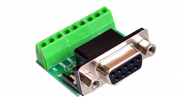
DESCRIPTION: The basic operation and setup of the DB9 Male Screw Terminal to RS232 RS485 Conversion Board are similar to the previously described DB9 Female version. Here's a general overview of the steps:
Identify the RS232 and RS485 devices: Determine the devices you want to connect using the conversion board. Understand the RS232 and RS485 wiring requirements and the specific pin assignments for your devices.
Connect the RS232 device: Use a standard RS232 cable to connect the RS232 device to the DB9 male connector on the conversion board. Ensure that you connect the appropriate signals (transmit, receive, ground, etc.) to their corresponding screw terminals on the board.
Connect the RS485 device: Connect the RS485 device to the other set of screw terminals on the conversion board. The wiring for RS485 typically includes two data wires (A and B) along with the ground wire.
Configure the conversion board (if necessary): If your conversion board has configuration options such as DIP switches or jumpers, set them according to the desired parameters for your specific application. Consult the board's documentation for guidance on configuration settings.
Power up the devices: Provide power to both the RS232 and RS485 devices involved in the communication. Ensure that the power supplies for both devices are properly connected and meet the required specifications.
Test the communication: Use appropriate software or code on the RS232 device and the RS485 device to establish communication. Configure the software with the correct baud rate, data format, and other necessary settings.